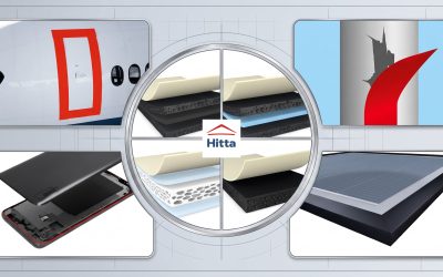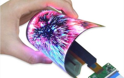
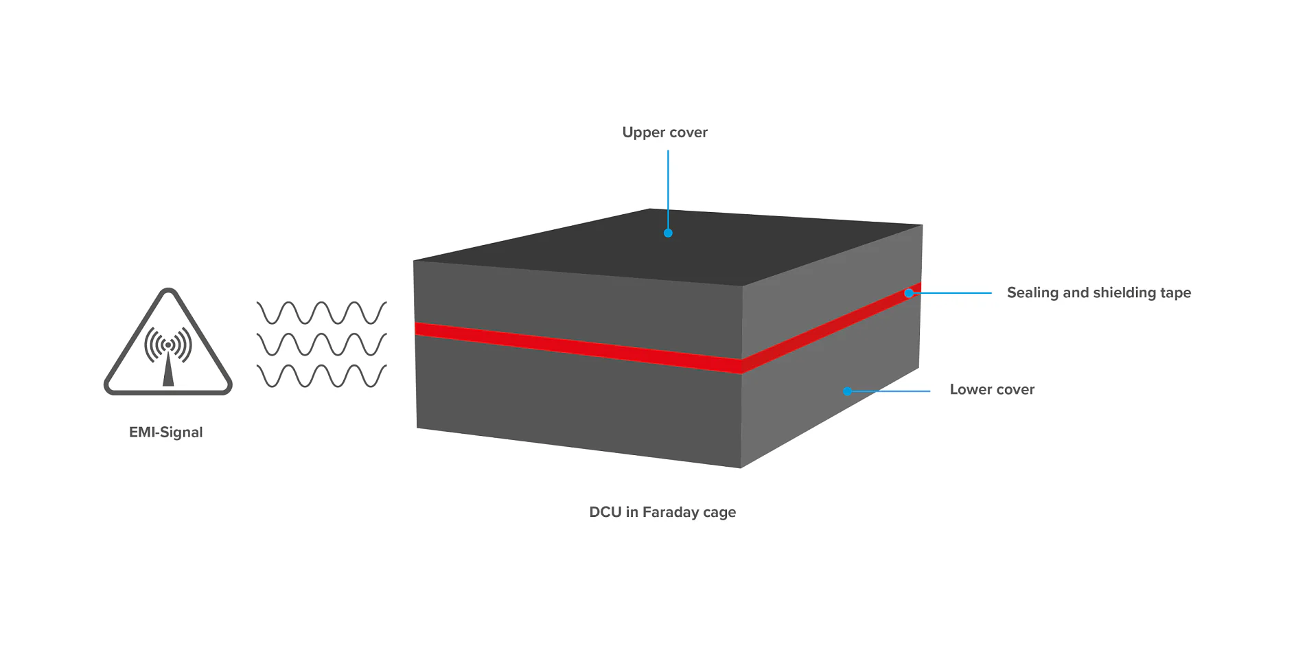
Solution Overview
Shielding tapes are designed to protect sensitive electronic components and devices from electromagnetic interference (EMI) and radio-frequency interference (RFI). These solutions help manufacturers meet electromagnetic compatibility (EMC) requirements while maintaining device performance, reliability, and functionality.
Key Benefits
- Effectively shields against electromagnetic interference (EMI) and radio-frequency interference (RFI).
- Creates a conductive electromagnetic shielding layer.
- Uses conductive materials such as copper and aluminum.
- Supports compliance with electromagnetic compatibility (EMC) requirements.
- Enables precise application, making it suitable for high-speed production lines.
- Can be integrated into bonding, fastening, and sealing applications.
Typical Applications
- Smartphones and tablets.
- Displays and OLED technology.
- Laptops, TVs, and display monitors.
- Wearable devices and electronic accessories.
- Smart home devices.
Value Delivered: Shielding tapes help protect electronic devices from electromagnetic interference, contributing to stable performance, improved reliability, and long-term operational stability.
Why Are EMI and RFI Major Concerns for Electronics Manufacturers?
EMI and RFI can directly affect the performance and reliability of electronic devices. Electromagnetic interference may cause components to malfunction or devices to operate erratically. In computers and data storage systems, such interference can lead to data errors, data corruption, or disruptions in data access.
EMI and RFI can also degrade signal transmission and reception, resulting in data errors or communication interruptions in radio, TV, and wireless network systems. In audio and video equipment, interference may manifest as static noise, visual artifacts, or degraded signal quality.
Therefore, controlling EMI and RFI is essential for ensuring stable and reliable device operation. Selecting an appropriate shielding solution, combined with proper circuit design, component placement, and grounding, helps minimize the effects of electromagnetic interference and meet product quality and reliability requirements.
Shielding Tape Solutions for Electronic Device Protection
Whether you manufacture smartphones, tablets, displays, OLED-based devices, laptops, TVs, wearable devices, electronic accessories, or smart home products, our electrically conductive tapes help enable the design of modern, compact, high-performance devices with integrated functionality.
Our product portfolio includes copper foil and aluminum foil shielding tapes specifically designed to protect electronic components and devices against electromagnetic interference (EMI) and radio-frequency interference (RFI). These products play an important role in protecting electronic systems by effectively shielding against external electromagnetic radiation.
Meeting electromagnetic compatibility (EMC) requirements is essential to ensuring product safety and reliability. Electronic devices must operate reliably in environments where interference is present, while keeping their own electromagnetic emissions within permitted limits.
This also presents a challenge for design engineers, particularly in power electronics systems. High-frequency switching can generate electromagnetic interference that affects both the performance of components and the operation of nearby equipment.
EMI shielding tape is one solution for controlling interference during the design and assembly process. When properly selected and applied, shielding tape can help protect sensitive areas, improve electrical continuity across joints, and support EMC compliance. Some specialized tape products also offer thermal conductivity to help transfer heat away from components. However, heat dissipation performance depends on each product’s material structure and thermal conductivity.
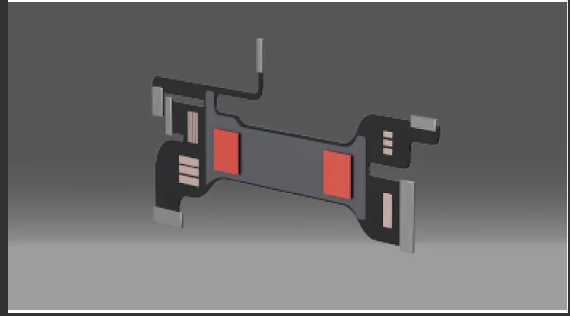
Foldable LP Static Render_GroundingShielding___Alt 3 1
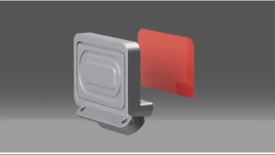
Foldable LP Static Render_GroundingShielding
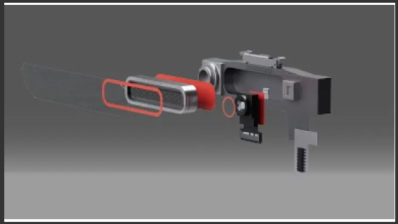
Foldable LP Static Render_GroundingShielding alt 1
Foldable LP Static Render_GroundingShielding alt 2
How Does EMI Shielding Tape Improve the Performance and Reliability of Electronic Devices?
EMI shielding tape helps minimize the effects of electromagnetic interference on electronic device operation. When correctly positioned and properly electrically bonded, the conductive tape layer can shield sensitive components, reduce the ingress of external interference, and limit electromagnetic emissions originating from within the device.
By reducing the impact of electromagnetic interference, this solution helps maintain signal integrity, minimize operational errors, and improve device reliability. Effective EMI control also helps manufacturers meet electromagnetic compatibility (EMC) requirements. However, actual performance depends on the tape material, application location, electrical contact quality, grounding design, and the overall device structure.
Key Factors to Consider When Selecting EMI Shielding Tape
Selecting the right EMI shielding tape requires evaluating its electrical properties, adhesion performance, backing material, and operating conditions. Since each application has different requirements, the selection should not be based on a single specification alone.
First, check the tape’s electrical conductivity and contact resistance, particularly when establishing a grounding connection or maintaining electrical continuity between metal surfaces. Next, evaluate its shielding effectiveness (SE), expressed in decibels (dB), across the frequency ranges relevant to the intended application.
Adhesion to the substrate must also be considered, along with resistance to heat, humidity, chemicals, and aging. For devices subject to electromagnetic compatibility (EMC) requirements, verify the applicable standards and review product test data obtained under relevant conditions.
For applications requiring thermal management, assess the tape’s thermal conductivity and heat transfer direction as well. Not all EMI shielding tapes provide effective heat dissipation, so the product should be selected according to the design requirements and actual assembly conditions.
Contact Information
HITTA JSC is the official authorized distributor of tesa in Vietnam. Our EMI shielding tape solutions are selected to meet the technical requirements of each application, helping mitigate electromagnetic interference and maintain electrical continuity at contact points when properly designed and applied.
Depending on the backing material and adhesive properties, these tapes can be used to shield components, address seams and joints in device enclosures, or establish electrical connections between conductive surfaces. Typical applications include consumer electronics, flexible printed circuit (FPC) assemblies, camera modules, and other assemblies requiring electromagnetic compatibility (EMC) control.
☎️ Hotline: 0565.336.879
✉️ Email: hitta@hitta.vn
What Is EMI Shielding Tape?
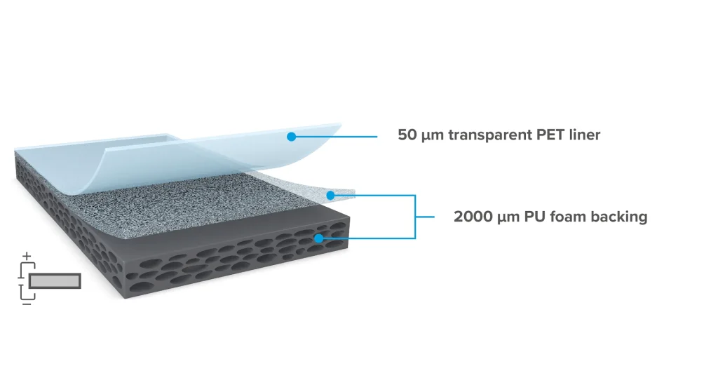
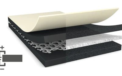
Electromagnetic interference (EMI) shielding tape is a specialized adhesive tape typically made with a metal foil or conductive fabric backing combined with a pressure-sensitive adhesive (PSA). It provides adhesion while helping shield electronic components and devices from electromagnetic interference.
Unlike conventional insulating tapes, EMI shielding tape is designed to provide an electrically conductive path and reduce electromagnetic interference through the reflection and absorption of electromagnetic waves. When applied to components, device enclosures, or around cables, it forms a shielding layer that helps limit external electromagnetic interference from entering the device while reducing emissions from within that could affect nearby equipment.
In modern electronic devices, EMI shielding tape is commonly used for three main purposes:
1. EMI Shielding: Helps limit external electromagnetic interference and reduce electromagnetic emissions from within the device through the reflection and absorption of electromagnetic waves.
2. Grounding: Provides an electrical path between surfaces or components that require grounding, helping conduct unwanted currents and dissipate static charge when properly connected to the ground (GND) system.
3. Seam Sealing: Covers joints and gaps between metal enclosures, chassis, or device components. This helps limit electromagnetic leakage through openings, particularly at locations where gaps may compromise overall EMI shielding effectiveness.
How EMI Shielding Tape Works
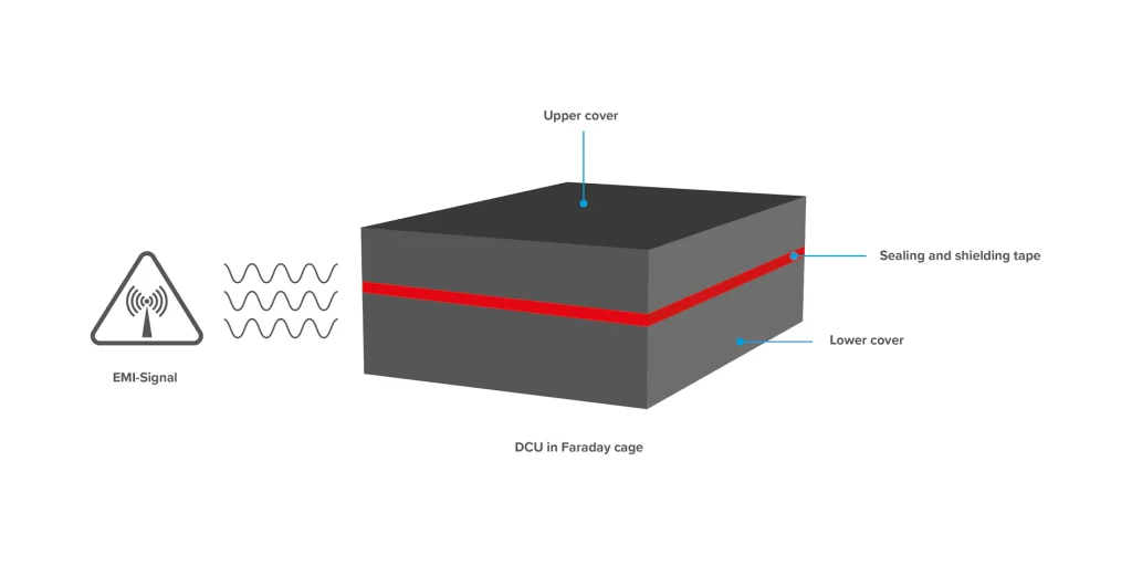
EMI shielding tape helps reduce electromagnetic interference through three main mechanisms: reflection, absorption, and grounding. The effectiveness of each mechanism depends on the backing material, tape construction, interference frequency, and installation method.
Electromagnetic Wave Reflection
When an electromagnetic wave encounters the conductive backing of a shielding tape, such as copper or aluminum, part of its energy is reflected back into the surrounding environment. This phenomenon occurs because of the difference in electromagnetic impedance between air and the conductive material.
As a result, the tape helps limit the amount of interference energy transmitted through the shielding layer, protecting sensitive electronic components and circuits. The degree of reflection depends on the material properties, wave frequency, and actual shielding configuration.
Electromagnetic Wave Absorption
Some of the wave energy that enters the material is further attenuated as it travels through the conductive layer. The electric and magnetic fields of the wave induce electrical currents within the material, converting part of the electromagnetic energy into heat.
This process reduces the intensity of the wave as it passes through the shielding material. The level of absorption depends on the material’s thickness, electrical conductivity, magnetic properties, and operating frequency. In many electronic applications, reflection and absorption work together to improve EMI shielding effectiveness.
Grounding
In addition to shielding against electromagnetic waves, certain types of EMI tape can provide electrical connections between metal components or between the shielding layer and the device’s grounding system.
With electrically conductive adhesive tape, current can flow through both the backing and the adhesive layer, depending on the product’s construction. When properly connected to a ground (GND) point, the tape provides a conductive path for unwanted currents and helps maintain electrical continuity between surfaces that require shielding.
This is particularly important at joints between device enclosures, metal chassis, and electronic circuit boards, where poor electrical contact can reduce shielding effectiveness. However, EMI shielding and grounding are related but distinct functions. Actual performance also depends on contact resistance, grounding architecture, and the overall system layout.
Common Types of EMI Shielding Tape and How to Select Them
EMI shielding tapes come in various types, differing in backing materials, construction, and the electrical conductivity of the adhesive. Each type is suited to specific requirements, from shielding metal surfaces to grounding, securing components, and treating seams and joints in electronic devices.
Flat Copper Foil Tape
- Construction: A flat copper foil backing combined with conductive or non-conductive acrylic adhesive.
- Properties: Copper offers high electrical conductivity, is easy to convert, and can be soldered when the product construction permits. Shielding effectiveness depends on foil thickness, adhesive properties, interference frequency, and electrical contact quality.
- Applications: EMI shielding on flat surfaces, grounding metal components, and applications requiring electrical connections. With non-conductive adhesive, a separate electrical contact solution is needed if conductivity through the adhesive layer is required.
Embossed Copper Foil Tape
- Construction: Copper foil with an embossed surface featuring specific patterns or structures, combined with an adhesive layer.
- Properties: Raised surface features can improve direct metal-to-metal contact when properly compressed. However, performance depends on the pattern design, applied pressure, mating surface, and adhesive construction.
- Applications: Areas requiring improved electrical contact between metal surfaces, grounding, or connections between EMI shielding components. Check the product’s contact resistance specifications to determine its suitability.
Aluminum Foil Tape
- Construction: An aluminum foil backing combined with acrylic or other adhesive systems, which may be electrically conductive or non-conductive.
- Properties: Aluminum is lightweight, electrically conductive, and easy to form. Its naturally occurring oxide layer must be considered when evaluating electrical contact and soldering. Conventional aluminum foil cannot be soldered directly in the same way as copper foil without an appropriate surface treatment or specialized process.
- Applications: Shielding large surfaces, device enclosures, cables, and structures where weight reduction is important. When selecting a product, distinguish aluminum tapes intended for insulation and sealing from those specifically designed for EMI shielding and electrical connections.
Tin-Plated Copper Foil Tape
- Construction: Copper foil coated with a layer of tin and combined with a suitable adhesive.
- Properties: Tin plating can improve solderability and help protect the copper surface against oxidation under suitable operating conditions. Corrosion resistance also depends on the environment, plating quality, and compatibility between contacting metals.
- Applications: Electronic assemblies requiring soldering, grounding, or stable electrical contact. These tapes may be considered for automotive and electronic devices operating in humid environments, subject to verification of temperature resistance and corrosion performance.
Conductive Fabric Tape
- Construction: A woven or nonwoven fabric backing plated with conductive metals, commonly copper, nickel, or combinations of conductive metals, combined with conductive or non-conductive adhesive depending on the product.
- Properties: Soft, lightweight, flexible, and conformable to curved surfaces or complex geometries. Compared with solid metal foil, conductive fabric may be better suited to applications requiring flexibility. However, abrasion resistance, repeated-flex durability, and shielding effectiveness must be evaluated against the product specifications.
- Applications: EMI shielding for cables, wire harnesses, laptop displays, and contact areas between device frames and shielding layers. For foldable devices, select a product with suitable repeated-flex performance for the intended design.
Double-Sided Conductive Tape and Conductive Transfer Tape
- Construction: Double-sided conductive tape has electrically conductive adhesive on both sides of a backing material. Conductive transfer tape, by contrast, primarily consists of a conductive adhesive layer without a separate backing.
- Properties: These tapes bond surfaces while providing an electrical path between them when the adhesive and contacting surfaces meet the required conductivity specifications. The backing-free construction of transfer tape helps minimize thickness, making it suitable for assemblies with limited installation space.
- Applications: Attaching EMI shielding cans, bonding metal sheets, securing shielding materials, and connecting surfaces that require grounding in electronic assemblies. Check through-thickness resistance and the ability to maintain electrical contact after assembly.
Selection Considerations: EMI shielding tape should not be selected based on backing material alone. Consider shielding effectiveness across the relevant frequency range, contact resistance, adhesive conductivity, thickness, temperature resistance, environmental conditions, and converting requirements.
In particular, conductive adhesive is not always necessary for EMI shielding, but it is essential when the bonded joint must also provide an electrical connection or grounding path.
Classification of Conductive Tapes by Electrical Conductivity Direction: XYZ and Z-Axis
In addition to the backing material, the direction of electrical conductivity through the adhesive is an important factor when selecting tapes for EMI shielding and grounding applications. Depending on the material construction, current may flow in multiple directions or primarily through the thickness of the adhesive layer.
Isotropic XYZ Conductive Tape
- Operating Principle: The adhesive contains conductive particles, such as metal particles or metal-coated particles, that form an electrically conductive network within the adhesive layer.
- Conductivity Characteristics: Conducts electricity along all three axes: X and Y across the surface, and Z through the thickness of the adhesive layer.
- Applications: Suitable for joints requiring electrical conductivity in multiple directions, such as bonding metal surfaces, establishing grounding connections, and maintaining electrical continuity between EMI shielding components.
Z-Axis Anisotropic Conductive Tape
- Operating Principle: The material is engineered to provide electrical conduction primarily perpendicular to the tape surface (the Z-axis), while limiting conductivity in the horizontal X and Y directions.
- Conductivity Characteristics: Enables electrical connections between two opposing surfaces while limiting current flow to adjacent locations. However, lateral insulation performance and the risk of short circuits must be evaluated based on product specifications, contact spacing, and assembly conditions.
- Applications: Suitable for fine-pitch connections where electrical conduction through the material thickness is required while limiting electrical connections between neighboring contact points. Depending on the design, this solution may be used in FPC assemblies and high-density electronic components.
Note: Z-axis conductive tape is not synonymous with every type of tape used for FPC grounding. Confirm that the product’s conductive structure meets the connection requirements and contact spacing of the intended application.
Tape Selection Guide Based on Technical Requirements
| Technical Requirement | Tape Type to Consider | Reason for Selection |
|---|---|---|
| Wrapping cables or covering curved surfaces where flexibility is required | Conductive Fabric Tape | Flexible, conformable to surface contours, and suitable for applications requiring adaptability |
| Directly soldering wires to the backing material | Copper Foil Tape or Tin-Plated Copper Foil Tape | Soldering may be possible when the backing material and product construction meet the requirements |
| Improving surface oxidation resistance | Tin-Plated Copper Foil Tape | Tin plating helps protect the copper surface under suitable operating conditions |
| Shielding large areas while optimizing cost and weight | Aluminum Foil Tape | Lightweight, easy to convert, and suitable for large surfaces |
| Connecting small contact points while limiting lateral conductivity | Z-Axis Anisotropic Conductive Tape | Provides through-thickness conductivity while limiting electrical connections between adjacent contact points |
| Bonding two metal surfaces while establishing an electrical connection | Double-Sided Conductive Tape or Conductive Transfer Tape | Combines bonding and electrical conductivity in a single material system |
Selection Principle: When electrical conductivity is required across multiple locations on a surface, isotropic XYZ conductive tape is generally worth considering. When a connection is needed between two opposing surfaces while electrical conduction between adjacent contact points must be limited, Z-axis anisotropic conductive tape may be more suitable.
In both cases, verify contact resistance, directional electrical resistance, and compatibility with the actual component structure before selecting a product.
Practical Applications of EMI Shielding Tape Across Industries
EMI shielding tape is used in a wide range of electronic devices to reduce electromagnetic interference, maintain grounding connections, and improve shielding performance in areas that are difficult to address using conventional methods. Depending on the device structure and technical requirements, solutions may use copper foil, aluminum foil, conductive fabric, or double-sided conductive tape.
Case 1: EMI Shielding and Grounding for Signal Cables and FPCs
Challenge: In smartphones, tablets, and laptops, flexible printed circuit (FPC) cables are often routed near antennas, displays, or camera modules. Electromagnetic interference generated by high-speed signal lines can affect sensitive circuits, while radio-frequency signals from antennas may also interfere with nearby electronic circuits. In some cases, this can reduce receiver sensitivity, a phenomenon known as receiver desense.
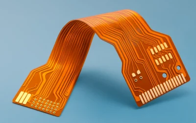
Solution: Copper foil tape or conductive fabric tape can be used to shield cables in selected areas. Where the shielding layer needs to connect to the device chassis or a grounding point on the circuit board, a suitable conductive tape can help maintain electrical continuity.
Benefits: This approach helps reduce emissions from cables and limit crosstalk between signal lines. Actual performance depends on the shielding configuration, grounding arrangement, and overall RF system design.
Case 2: EMI Shielding for Seams and Joints in Device Enclosures and Metal Housings
Challenge: Industrial electronic enclosures, industrial control computers, and controllers often consist of multiple assembled metal parts. Gaps or discontinuities in electrical contact between these parts can reduce EMI shielding effectiveness, allowing electromagnetic energy to leak through the joints.
Solution: After cleaning the contact surfaces, engineers can apply conductive fabric tape or suitable metal foil tape to areas requiring shielding and electrical continuity. For joints that require stable electrical contact, the material must provide appropriate contact resistance and be installed with the required compression.
Benefits: This solution helps improve electrical continuity between metal components, reduce interference leakage through seams, and enhance enclosure shielding effectiveness. Compliance with EMC requirements must be verified through testing of the completed product.
Case 3: Grounding for Touchscreens and Mobile Devices
Challenge: Touchscreen assemblies contain components that are sensitive to electromagnetic interference and electrostatic discharge (ESD). Inadequate grounding or shielding design may cause induced noise, unstable operation, or touchscreen errors under certain operating conditions.
Solution: Copper foil tape or conductive tape can be used to connect shielding layers, display edges, and the device’s metal frame. The material must be compatible with the display construction, assembly clearances, and insulation requirements of adjacent areas.
Benefits: When properly designed, the conductive path and shielding layer help reduce interference affecting the display assembly while supporting ESD control. However, ghost touch issues can also originate from software, the touch controller, or other causes, so EMI tape alone cannot resolve every case.
Case 4: EMI Control in Electric Vehicles (EVs) and Battery Systems
Challenge: Electric vehicles use inverters, power converters, and high-power electric drive systems. Rapid voltage and current switching can generate electromagnetic interference that affects communication systems, sensors, and electronic control circuits if shielding and grounding are inadequate.
Solution: Copper foil tape, tin-plated copper foil tape, or conductive fabric tape can be used for localized shielding, electrical connections between components, and contact points within electronic assemblies. For wiring harnesses, shielding materials must be selected according to temperature requirements, mechanical durability, abrasion resistance, and the operating environment.
Benefits: These solutions help reduce radiated emissions and limit interference coupled into sensitive signal lines. In EV applications, materials must meet the relevant technical and safety requirements. EMI shielding tape does not replace high-voltage insulation or dedicated electrical safety measures.
Case 5: EMI Shielding for 5G, Wi-Fi, and IoT Modules
Challenge: Modern electronic circuit boards often place CPUs, memory, and RF transceiver modules within limited space. Noise from digital processing circuits, switching power supplies, or high-speed transmission lines can couple into sensitive areas, affecting signal quality and device performance.
Solution: Double-sided conductive tape or conductive transfer tape can be used to attach metal shielding components to the device frame or enclosure. Copper foil tape and conductive fabric tape can also provide localized shielding where appropriate for the design.
Benefits: When combined with proper circuit layout, grounding, and shielding design, these solutions help reduce interference coupling between functional blocks and improve electromagnetic compatibility (EMC). Actual data transmission performance still depends on antenna design, RF characteristics, and overall system quality.
Case 6: EMI Shielding in Medical Devices and Industrial Electronics
Challenge: Devices such as electrocardiographs (ECG), electroencephalographs (EEG), and industrial measurement systems must process low-amplitude signals. Electromagnetic interference from power supplies, motors, or nearby equipment can affect measurement signal quality and the reliability of results.
Solution: Copper foil tape, aluminum foil tape, or specialized conductive materials can be used to create an internal shielding layer within an equipment enclosure, including plastic housings. The shielding layer must be designed with appropriate electrical contact points and connected to the grounding system or reference point as required by the device.
Benefits: This approach helps reduce electromagnetic interference entering measurement circuits, improve the signal-to-noise ratio (SNR), and support measurement stability. For medical devices, material selection and placement must comply with applicable electrical safety, leakage current, and EMC requirements. Shielding layers should not be connected arbitrarily to protective earth (PE).
Implementation Note: EMI shielding tape performs best when selected for the specific application and integrated during the design stage. Key parameters include shielding effectiveness across relevant frequencies, contact resistance, adhesive construction, mechanical durability, temperature resistance, and grounding strategy. For demanding applications such as automotive, telecommunications, and medical equipment, performance should be validated through EMC testing of the assembly or complete device.
How to Select EMI Shielding Tape Based on Technical Requirements
Selecting the right electromagnetic interference (EMI) shielding tape requires evaluating the interference characteristics, environmental conditions, safety requirements, and assembly structure together. No single tape is suitable for every application; selection should be based on technical specifications and actual test results.
Selection Based on the Frequency Range to Be Shielded
Shielding effectiveness (SE) is typically expressed in decibels (dB). A higher value indicates greater attenuation of electromagnetic energy under the corresponding test conditions. However, actual performance depends on frequency, backing material, thickness, adhesive construction, gaps, and grounding connection quality.
- Low frequencies (below 10 MHz): For low-frequency magnetic field interference, particular attention should be paid to the material’s magnetic properties, distance from the noise source, and current path geometry. Increasing copper foil thickness may improve certain electrical properties, but does not guarantee effective magnetic field shielding in every situation. For specialized applications, materials with high magnetic permeability may be worth considering.
- Mid-range frequencies (10 MHz to 1 GHz): Copper foil or aluminum foil tape can meet the requirements of many EMI shielding applications. Check SE values across the target frequency range rather than assuming that every product achieves 60–80 dB.
- High frequencies (above 1 GHz, including Wi-Fi 6E and 5G applications): Electrical contact quality, gaps, joints, and grounding layout can significantly affect shielding effectiveness. Prioritize products with test data at the actual operating frequencies, and verify shielding continuity after assembly.
Selection Based on the Operating Environment
Temperature, humidity, and chemicals can affect adhesion, backing durability, and contact resistance throughout the device’s service life.
- Indoor environments under normal conditions: Copper or aluminum foil tape with acrylic adhesive may be suitable if it meets adhesion and conductivity requirements.
- High-temperature environments: Check the product’s continuous operating temperature, peak temperature, and exposure duration. Specialized silicone or acrylic adhesives may be suitable depending on the application, but selection should not be based on adhesive type alone.
- Humid or corrosive environments: Tin-plated copper foil or materials with suitable surface protection may be considered. However, plating does not automatically guarantee corrosion resistance in every environment. Compatibility between metals, adhesives, and actual operating conditions must also be evaluated.
Selection Based on Flame Retardancy and Electrical Safety Requirements
In electronic devices, automotive systems, and aerospace applications, shielding materials must meet the safety requirements relevant to their intended use.
When selecting EMI tape, review its flame-retardancy data, certification scope, and the specific material construction that was tested. For example, the UL 94 V-0 classification indicates self-extinguishing performance under specified test conditions. It does not mean that a product is completely non-combustible or can prevent every fire-related incident.
Other factors include the insulation properties of related components, thermal durability, and the risk of electrical short circuits within the assembly. In particular, conductive EMI shielding tape cannot replace insulation materials or dedicated electrical safety barriers.
Selection Based on Mechanical Requirements and Adhesion
Flexibility, bend resistance, and adhesion determine whether the tape can maintain shielding performance after assembly and throughout long-term use.
- Flat surfaces with minimal deformation: Copper or aluminum foil tape is generally suitable for fixed shielding locations where application is straightforward.
- Curved surfaces, edges, or cables requiring flexibility: Conductive fabric tape may be suitable because it conforms to surface contours. For locations subject to repeated flexing, check fatigue resistance and plating durability.
- Plastic surfaces that are difficult to bond: Consider the substrate’s surface energy, adhesive type, adhesive thickness, and peel adhesion. Some low-surface-energy plastics require specialized adhesives or surface treatment before application.
In addition to peel adhesion, evaluate adhesion after heat and humidity aging, as well as the ability to maintain contact resistance, to ensure that the bond meets application requirements.
In summary, EMI shielding tape selection should begin with the target frequency range and grounding requirements, followed by an assessment of environmental conditions, safety requirements, and converting capabilities. For critical applications, request test data for the specific product grade rather than relying solely on general descriptions of the material.
Standards for Evaluating and Testing EMI Shielding Tape Quality
To evaluate the electromagnetic shielding performance of EMI tape, it is important to distinguish between testing the material properties and assessing the shielding effectiveness of the complete device. Flame retardancy and electrical safety requirements must also be evaluated against the standards applicable to the intended application.
ASTM D4935: Measuring the Electromagnetic Shielding Effectiveness of Materials
ASTM D4935 is a test method used to determine the electromagnetic shielding effectiveness of planar materials under specified measurement conditions. It may be referenced when evaluating the substrate or construction of EMI shielding tape, provided the material falls within the scope of the standard.
- Test method: The material specimen is placed in a coaxial transmission-line holder. The measuring equipment determines the attenuation of the electromagnetic signal with the specimen in place compared with a reference condition.
- Frequency range: The traditional ASTM D4935 method primarily covers frequencies from approximately 30 MHz to 1.5 GHz. The applicable standard edition and test configuration should be verified before determining the specific scope of application.
- Unit of measurement: Shielding effectiveness (SE) is expressed in decibels (dB). Higher values indicate greater electromagnetic signal attenuation under the corresponding test conditions.
EMI shielding tape should not be classified by quality based solely on a fixed dB threshold. Results also depend on the measurement frequency, specimen construction, sample preparation, and test method. In particular, measurements taken on a material alone do not fully represent the shielding effectiveness of the tape after it has been applied to a device.
IEEE 299: Evaluating the Shielding Effectiveness of Enclosures
Unlike ASTM D4935, which focuses on planar materials, IEEE 299 is designed to evaluate the electromagnetic shielding effectiveness of enclosures, such as electromagnetic shielding rooms and larger shielding structures.
Test method: Measure the attenuation of electromagnetic fields between the outside and inside of the shielding structure at specified locations, frequencies, and test conditions.
Frequency range: IEEE 299-2006 covers frequencies from 9 kHz to 18 GHz, with possible extensions under the applicable standard conditions. This edition is now inactive and archived, so the applicable version should be verified before developing a test plan.
Applications: Evaluating the shielding effectiveness of equipment enclosures or structures of an appropriate size. For smaller electronic enclosures, IEEE 299.1-2013 is a related standard covering enclosures with dimensions ranging from 0.1 m to 2 m.
In practice, this method helps assess the performance of the complete assembled structure, including joints and gaps sealed with EMI shielding tape. However, the test method must be selected according to the dimensions and construction of the device. IEEE 299 should not be applied by default to every product.
UL 510: A Standard Related to Electrical Insulation Tape
UL 510 covers electrical insulating tapes made from PVC, polyethylene, and rubber for use in wire and electrical joint insulation within the scope of the standard. It is not a standard for measuring EMI shielding effectiveness.
When evaluating EMI shielding tape for electronic devices, the following requirements must be clearly distinguished:
- EMI shielding effectiveness: Evaluate using a shielding effectiveness measurement method appropriate for the material or enclosure.
- Flame retardancy: Test according to the fire performance standard applicable to the material and application, such as UL 94 where appropriate.
- Electrical insulation: Determine compliance according to the standard applicable to the specific tape type and intended use.
Therefore, EMI shielding tape should not automatically be considered flame-retardant certified or compliant with electromagnetic shielding requirements simply because it meets UL 510. The certification and scope of application for each product grade must be verified.
Key considerations when evaluating EMI shielding tape quality: No single standard is sufficient to confirm a product’s overall performance across all applications. For materials, ASTM D4935 may be referenced; for shielding enclosures, an appropriate method such as IEEE 299 or IEEE 299.1 should be selected. It is also advisable to evaluate adhesion, contact resistance, the ability to maintain electrical continuity after aging, and shielding effectiveness on the actual assembled product.
Guidelines for Proper Installation of EMI Shielding Tape
EMI shielding effectiveness depends not only on the type of tape used but also on surface preparation, application pressure, and electrical contact quality. Improper installation may allow the tape to adhere securely while failing to meet shielding or grounding requirements.
Surface Preparation and Cleaning
Dust, grease, fingerprints, and electrically insulating coatings can reduce adhesion or increase contact resistance between the tape and the metal surface.
- Clean the surface: Use a lint-free cloth and a suitable solvent, such as IPA (Isopropyl Alcohol), in accordance with the manufacturer’s instructions. Ensure the solvent is compatible with the substrate and allow the surface to dry completely before application.
- Check electrical contact points: If grounding is required, identify locations where direct contact with conductive metal can be established. Paint, anodizing, and oxide layers may impede electrical conductivity. Remove coatings only when permitted by the design and supported by an appropriate process.
- Verify surface condition: The surface must be clean and dry, without burrs or defects that could cause edge lifting, tape wrinkling, or interrupted electrical contact.
Tape Application and Proper Pressure
EMI shielding tapes commonly use a pressure-sensitive adhesive (PSA). Adhesion and electrical contact performance depend on the tape construction, adhesive properties, substrate material, and application conditions.
- Remove the release liner: Peel off the liner gradually, avoiding contact with the adhesive to minimize contamination.
- Position and apply the tape: Place the tape in the correct position, then use a suitable roller or application tool to apply uniform pressure from the center toward both edges, minimizing wrinkles and air bubbles.
- Control application pressure: Apply consistent pressure in accordance with the manufacturer’s recommendations. A single fixed pressure should not be applied to every tape type, as requirements may vary depending on the adhesive layer, backing material, and surface geometry.
For tapes with conductive adhesives, appropriate application pressure helps increase the contact area between the adhesive and the conductive surface. However, pressure alone cannot overcome an insulating paint layer or compensate for an unsuitable grounding design.
Common Installation Errors
- Applying tape over paint or insulating coatings: This can interrupt the electrical conduction path and prevent the grounding connection from meeting requirements. Design suitable electrical contact points rather than assuming that conductive adhesive can penetrate insulating coatings.
- Leaving wrinkles or air bubbles: These reduce the contact area and may create gaps at joints, affecting shielding effectiveness, particularly at high frequencies.
- Applying insufficient or uneven pressure: This can result in poor surface contact, increased contact resistance, and reduced adhesion.
- Overstretching conductive fabric tape: Excessive stretching can deform the conductive fabric structure, affecting shielding uniformity and mechanical stability. Follow the surface contours without applying excessive tension.
After installation, inspect adhesion, electrical continuity, and contact resistance at connection points. For applications with stringent EMC requirements, shielding effectiveness should be evaluated on the actual assembled product rather than relying solely on the specifications of the tape itself.