Solution Summary
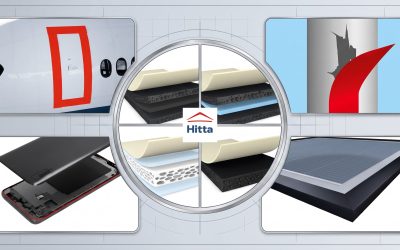
HITTA JSC is an official distributor of tesa in Vietnam. The ultra-thin tesa adhesive tapes distributed by HITTA deliver outstanding bonding performance at thicknesses as low as 5 μm. They are optimized for mounting FPCs, antennas, functional membranes, and complex structures within electronic components such as speakers, camera modules, and other applications.
These microscale component bonding solutions are specifically designed for confined spaces and curved surfaces, offering the following key benefits:
- Anti-repulsion and high conformability: PET-based tape solutions for general mounting applications.
- Superior bonding strength in small areas: Structural bonding solutions.
- High temperature resistance: Non-woven tape solutions.
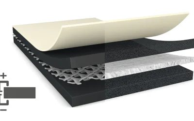
- Excellent electrical conductivity: Electrically conductive tape (ECT) solutions.
Designed for the next generation of electronic components, tesa’s bonding solutions distributed by HITTA support a wide range of formats, materials, surfaces, and applications. They address emerging component designs used in FPCs, antennas, speakers, sensors, and camera modules.
tesa’s application experts also bring extensive cross-device experience, helping reduce waste from repeated trials and optimize material usage.
Solutions for the Next Generation of Electronic Components
- Structural Bonding Solutions: Heat-activated adhesive films (HAF) and LTR tapes.
- Electrically Conductive Tape (ECT) Solutions: Conductive tapes for electrical connection applications.
- Removable Bonding Solutions: tesa Bond & Detach® tapes enable easy component removal for repair or rework without leaving adhesive residue on component surfaces.
- High-Temperature-Resistant Non-Woven Tapes: Designed to withstand reflow soldering processes in FPC manufacturing.
Applications of Flexible Printed Circuit (FPC) Bonding Tape Solutions
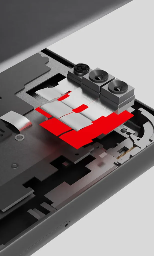
Component Bonding Solutions:
- General component mounting.
- Bonding FPCs and antennas to curved surfaces.
- Securing FPCs before SMT reflow soldering.
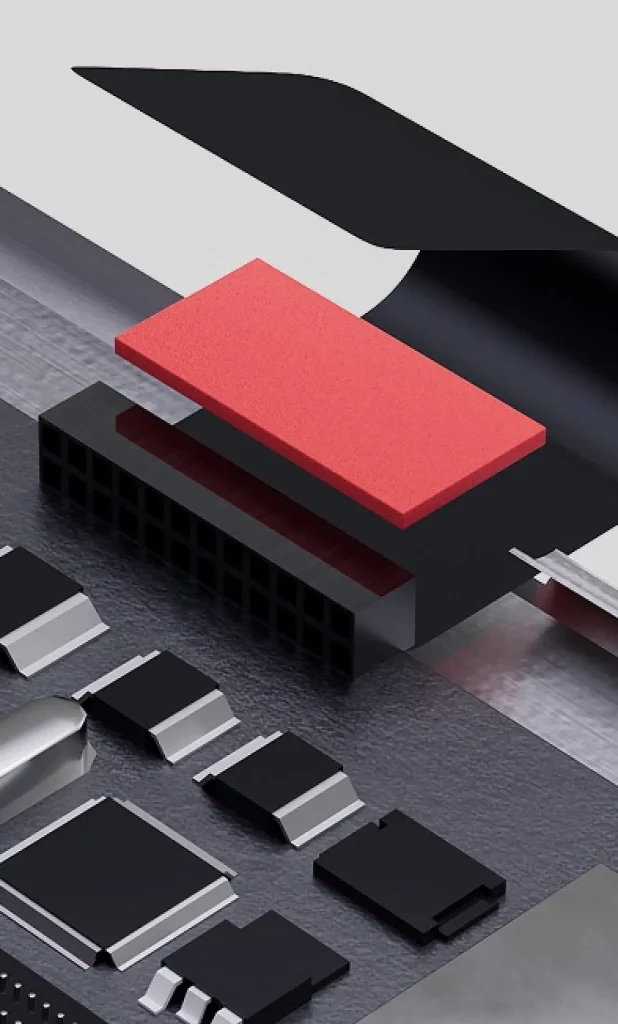
Component Shielding and Grounding Solutions:
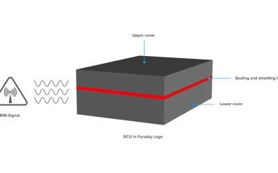
- Electromagnetic shielding and component grounding.
- Bonding and grounding in small areas using EC-HAF / EC-LTC solutions.
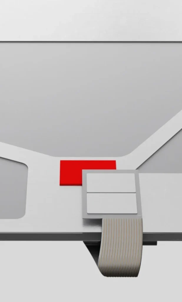
Specialized Component Bonding Solutions:
- Bonding FPCs to curved surfaces.
- Bonding functional membranes.
- Sensor bonding using LTC, LTR, and HAF tapes.
- Bonding speaker domes within speaker modules using light-curing adhesive tapes.
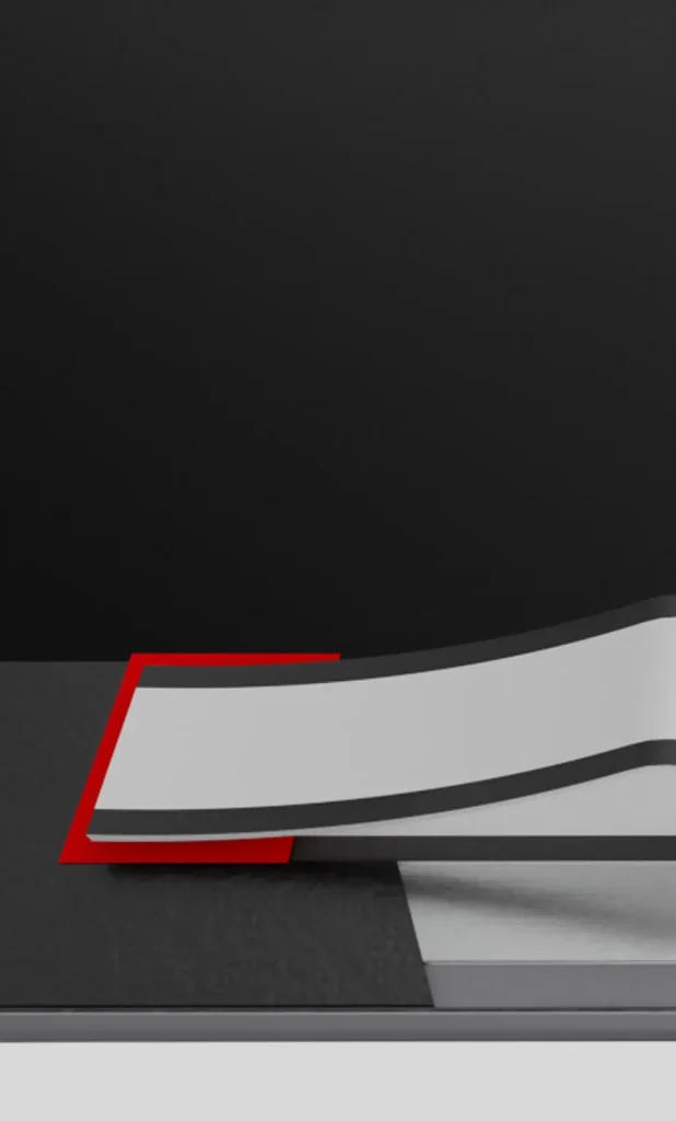
Removable Bonding Solutions:
- Residue-free bonding and removal with tesa Bond & Detach®.
- Bonding FPCs for side keys.
Contact HITTA
HITTA works with manufacturers to evaluate technical requirements and select suitable FPC adhesive tape solutions based on circuit design, substrate materials, thermal conditions, and assembly processes.
With tape converting capabilities, HITTA provides customized tape processing services, including die-cutting, slit-to-width converting, finger-lift design, and spool winding, supporting manual, semi-automatic, and fully automated assembly processes.
Our technical team helps evaluate key factors such as adhesion, heat resistance, mechanical strength, EMI shielding performance, electrical conductivity, and material compatibility. From material selection and sample testing to assembly process optimization, we aim to improve bonding consistency, reduce manufacturing defects, and optimize production costs.
If your company is looking for adhesive tape solutions for FPC stiffener bonding, PI/SUS/FR-4 stiffener attachment, EMI shielding, electrical connections, or ACF applications in electronic assembly, HITTA is ready to help you identify materials that meet your technical requirements and actual production conditions.
Contact HITTA today for technical consultation on FPC adhesive tape solutions tailored to your application.
- ☎️ Hotline: 0565.336.879
- ✉️ Email: hitta@hitta.vn
FPC and the Requirements of High-Density Electronic Assembly
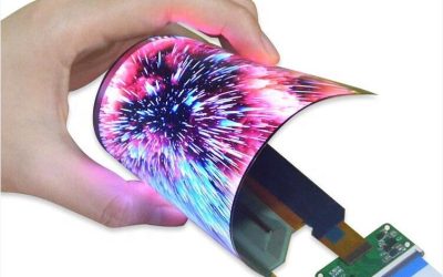
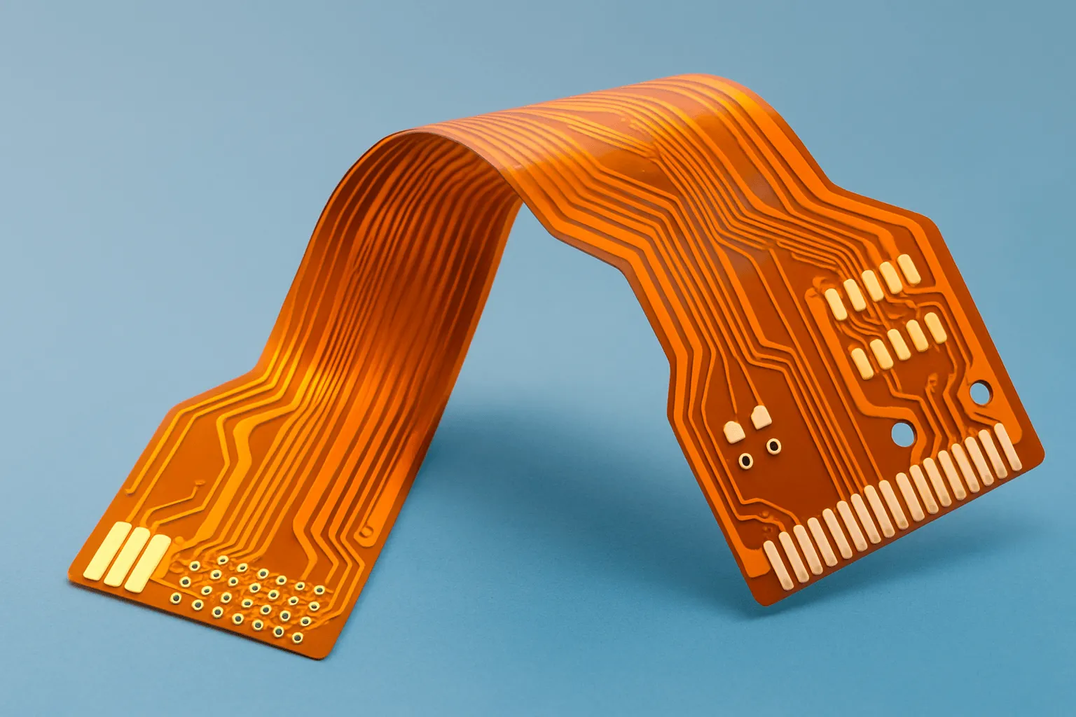
Flexible Printed Circuits (FPCs) are widely used in smartphones, wearable devices, automotive electronics, and communication equipment. Compared with conventional rigid PCBs, FPCs can bend and flex, fit into confined spaces, and help reduce weight while optimizing assembly space.
However, thin circuit substrates such as Polyimide (PI) and Polyester (PET) have limited stiffness and can deform under connector insertion and removal forces or repeated bending. As component density and signal transmission speeds increase, the requirements for mechanical reinforcement, interlayer bonding, grounding, and electromagnetic interference (EMI) shielding also become more demanding.
Specialized adhesive tapes and functional bonding films for FPCs help meet these requirements without significantly increasing assembly thickness or weight.
Key Technical Parameters for Selecting FPC Adhesive Tapes
Material selection should be based on the operating environment, FPC construction, and assembly process. Key parameters include:
- Heat resistance: Evaluate the temperatures and exposure times the material can withstand during manufacturing, particularly during lead-free reflow soldering. A temperature of 260°C is not a universal requirement for all adhesive tapes and must be verified against the specifications of each product and the actual process conditions.
- Adhesion and bond strength: Peel strength and shear strength indicate how well a bond can withstand tensile forces, sliding forces, vibration, and bending.
- Contact resistance and surface resistance: These parameters are important for electrically conductive materials and affect electrical grounding, conductivity, and EMI shielding performance.
- Dielectric properties: The Dielectric Constant (Dk) and Dissipation Factor (Df) should be considered in high-frequency signal transmission applications, where material properties can affect signal loss.
- Outgassing and VOC content: These factors are important in sensitive electronic assemblies, particularly camera modules and optical devices, where condensation or volatile residues may cause surface fogging or affect component performance.
Main Categories of Adhesive Tape Solutions for FPCs
Depending on assembly requirements and intended functions, FPC bonding materials can generally be classified into four main categories:
- Pressure-Sensitive Adhesive (PSA) Tapes: These tapes bond under light pressure at room temperature and are commonly used for stiffener attachment, securing FPCs to device housings, and bonding other components.
- Heat-Activated Films (HAF): These films are activated by heat and pressure to form durable bonds. Depending on their formulation, HAF materials can provide the heat resistance required for reflow soldering and resistance to certain chemicals.
- Electrically Conductive Tapes (ECT) and EMI Shielding Materials: These materials support grounding, provide electrical conduction paths, and reduce electromagnetic interference. Their conductivity depends on the backing and adhesive construction, which may incorporate metal foil, conductive fabric, or electrically conductive adhesive.
- Anisotropic Conductive Films (ACF): These films contain conductive particles dispersed in an adhesive matrix, allowing electrical current to pass through the thickness direction (Z-axis) at contact points while limiting conductivity in the horizontal plane (XY directions). ACF is commonly used to connect FPCs to displays and components with very fine contact pitches, serving as an alternative to certain conventional mechanical interconnection or soldering methods.
High-Temperature Pressure-Sensitive Adhesive (PSA) Tapes
Pressure-Sensitive Adhesive (PSA) tapes commonly use acrylic adhesives because of their good adhesion, stability, and compatibility with a wide range of surfaces, including Polyimide (PI) and metals. They form a bond under light pressure at room temperature without requiring heat activation.
In FPC applications, PSA tapes generally come in two main types:
Adhesive Transfer Tapes: These consist of an adhesive layer without a carrier, protected by a release liner. Their thin, flexible construction makes them suitable for bonding FPCs to device housings or other components where assembly space is limited.
Double-Coated Tapes: These feature adhesive layers on both sides of a carrier, such as PET film or nonwoven fabric. The carrier improves dimensional stability and facilitates die-cutting and automated assembly. Depending on the construction, these tapes can also be used to attach stiffeners before subsequent manufacturing processes.
For applications involving SMT reflow, select a PSA tape with heat resistance suitable for the actual peak temperature and exposure time. Not all PSA tapes can withstand reflow temperatures of 260°C.
Heat-Activated Films (HAF)
When an FPC needs to be bonded securely to a stiffener or a component subjected to mechanical loads, Heat-Activated Film (HAF) is an option worth considering.
Unlike PSA, HAF typically exhibits little or no tack at room temperature. When heated and pressed under specified conditions, the film softens, conforms to the substrate surfaces, and forms a bond. Some HAF systems use nitrile rubber (NBR) combined with phenolic resin; the exact composition and curing mechanism depend on the product formulation.
The bonding process generally involves two stages:
- Pre-lamination: Heat and pressure are applied to attach the film to the surface and hold the components in position before the bond is fully developed.
- Final Thermocompression Bonding: Temperature, pressure, and bonding time are controlled according to the manufacturer’s recommendations to achieve the required bond strength.
After curing, HAF can provide strong bonds with good heat and chemical resistance, making it suitable for FPC stiffener bonding with stainless steel (SUS), FR-4, or aluminum. For heat-sensitive materials such as PET and ABS, select an HAF system with a suitable processing temperature to minimize substrate deformation.
Parameters such as bonding temperature, pressure, curing time, and shear strength must be verified for each product. A single set of processing parameters should not be applied to all HAF systems.
Reworkable / Re-peelable Tapes
In electronic devices that require repair, component replacement, or disassembly for recycling, reworkable tapes can simplify removal compared with permanent bonding systems.
Depending on the design, these tapes may combine acrylic adhesive with a carrier film or a reinforced construction to maintain adhesion during service while allowing removal when needed.
Clean removability depends on the adhesive type, substrate material, bonding duration, and service conditions. Practical testing is therefore necessary to verify peel force, adhesive residue, and the ability to protect the FPC during removal.
These solutions are suitable for electronic assemblies that require maintenance or component replacement. They can help reduce damage during disassembly and support material recovery.
Comparison of FPC Adhesive Tape Solutions
| Criteria | Adhesive Transfer Tape | Double-Coated Tape | HAF | Low-Temperature HAF | Reworkable Tape |
|---|---|---|---|---|---|
| Bonding mechanism | Pressure at room temperature | Pressure at room temperature | Heat and pressure | Heat activation under a specific process | Pressure at room temperature |
| Construction | Adhesive without a carrier | Adhesive on both sides of PET or nonwoven carrier | Reactive heat-activated adhesive film | Specialized heat-activated film system | Adhesive with a removal-supporting construction |
| Main advantages | Thin and flexible | Dimensional stability and easy die-cutting | Strong structural bonding | Reduced thermal load on heat-sensitive substrates | Facilitates repair and disassembly |
| Heat resistance | Depends on adhesive type | Depends on adhesive and carrier | Depends on the HAF system after curing | Depends on formulation and service conditions | Depends on adhesive type |
| FPC applications | Bonding FPCs to device housings | FPC attachment and reinforcement | Bonding SUS, FR-4, or aluminum stiffeners | Bonding to suitable heat-sensitive substrates | Assemblies requiring removal or repair |
Technical note: Thickness, reflow resistance, peel strength, and shear strength do not have universal values for each material category. When selecting a product, compare its datasheet with the substrate materials, SMT process, and actual operating conditions.
Mechanical Reinforcement for FPCs
FPC Stiffener Layer Structure
Because FPCs are thin and flexible, they can deform or become damaged in areas that require greater rigidity, such as ZIF connectors, gold fingers, and SMT component mounting zones. To increase local stiffness, manufacturers typically attach a stiffener to the back of the circuit.
A typical reinforcement structure consists of:
- Circuit and component layer: Includes copper traces, contact pads, and electronic components.
- FPC substrate: Typically made of electrically insulating Polyimide (PI) film.
- Bonding layer: Pressure-Sensitive Adhesive (PSA) tape or Heat-Activated Film (HAF), depending on assembly requirements.
- Stiffener: May be made of PI, FR-4, stainless steel (SUS), or aluminum.
Selecting the appropriate stiffener material and bonding layer helps provide the required rigidity in specific areas while preserving flexibility elsewhere.
Polyimide (PI) Stiffeners for ZIF Connectors and Gold Fingers
PI stiffeners are commonly used in FPC connector areas where precise thickness control is required, such as display circuits and smartphone battery circuits. PI has thermal properties compatible with PI-based FPC substrates, which can help minimize thermally induced dimensional differences when the overall material structure is properly selected.
Primary function: To increase stiffness in the contact area, helping the FPC remain securely positioned in the ZIF connector and maintain reliable electrical contact. The total thickness of the connector area must meet the design specifications, which vary according to the connector type and FPC construction.
Bonding solutions: Acrylic PSA double-coated tapes or thin HAF films, selected according to thickness requirements, heat resistance, and manufacturing processes.
FR-4 Stiffeners for SMT Component Areas
In areas containing ICs, board-to-board (B2B) connectors, or other SMT components, the FPC needs sufficient rigidity to minimize deformation during assembly and operation. Excessive circuit bending can transfer stress to component leads and potentially damage solder joints.
FR-4 stiffeners, made from glass-fiber-reinforced epoxy composite, provide a rigid and stable support surface for these areas. Their thickness is selected according to design requirements and available assembly space.
Bonding solutions: PSA or HAF compatible with the substrate materials and manufacturing process. For applications requiring strong bonds that withstand SMT processing temperatures, verify the heat resistance and dimensional stability of the entire bonded structure after lamination.
Stainless Steel (SUS) and Aluminum Stiffeners
When higher rigidity is required within a limited space, or when localized heat transfer is needed, SUS and aluminum stiffeners are worth considering.
- SUS: Increases rigidity and protects the FPC against pressing forces and mechanical impacts in areas such as camera modules, sensors, and device edges. The magnetic properties of the selected stainless steel grade should be considered when designing around magnetic sensors or wireless charging coils.
- Aluminum: Offers low weight and good thermal conductivity, making it suitable for designs requiring localized heat spreading. Actual performance depends on contact area, assembly structure, and the thermal path.
Bonding solutions: Heat-resistant PSA or HAF, depending on bond strength requirements and processing temperatures. If electrical continuity between the metal stiffener and the FPC ground (GND) layer is required, a suitable conductive bonding structure must be used, and contact resistance should be verified after assembly.
Two-Stage Thermocompression Bonding Process Using HAF
When using Heat-Activated Film (HAF), the reinforcement process typically involves pre-lamination followed by final thermocompression bonding. Processing conditions must follow the datasheet for the specific film.
Step 1: Pre-lamination
The HAF film is placed on the PI, FR-4, or SUS stiffener, then heated and pressed to establish an initial bond and hold the film in position for subsequent processing. Some HAF systems allow pre-laminated parts to be stored before final bonding, provided the manufacturer’s storage requirements are followed.
Step 2: Final Thermocompression Bonding
After handling the release liner according to the product instructions, the stiffener is aligned with the FPC and placed in a thermocompression bonding machine. Bonding temperature, pressure, and time must be set according to the HAF type, substrate materials, and total assembly thickness to achieve the required bond strength.
Cooling and Bond Stabilization: For HAF systems that require pressure-assisted cooling, maintain pressure during the cooling stage as specified by the process. This helps minimize warpage and reduce the risk of gaps or delamination caused by thermal stress.
Electromagnetic Interference (EMI/RFI) Shielding and Grounding for FPCs
Shielding Mechanisms and High-Speed Signal Protection
High-speed data interfaces such as MIPI DSI/CSI, PCIe, and USB4, along with 5G wireless systems, place increasingly stringent demands on signal integrity in Flexible Printed Circuits (FPCs).
Due to their thin structure and trace layout, FPCs can emit or receive electromagnetic interference (EMI), potentially affecting signal quality and device performance.
Electrically conductive tapes and EMI shielding films help reduce interference through reflection, absorption, or conduction of interference currents to ground (GND), depending on the material structure. Actual shielding performance depends on the frequency range, shielding-layer design, and GND connection method.
Isotropic Electrically Conductive Tapes
Isotropic electrically conductive tapes (ICA/ECT) provide electrical conductivity in both the through-thickness direction (Z-axis) and the in-plane directions (XY), making them suitable for applications requiring electrical bonding and grounding.
Material structure: These tapes typically consist of a conductive adhesive containing metal particles such as nickel, copper, or silver, combined with a backing made of copper foil, aluminum foil, or conductive fabric. The specific composition varies by product.
Notable constructions include:
- Tin-Plated Copper Foil: The tin layer protects the copper surface and can improve solderability in suitable applications. Contact resistance and stability under hot and humid conditions should be verified against product specifications and actual application testing.
- Embossed Metal Foil: Raised features on the metal surface can penetrate a non-conductive adhesive layer under appropriate compression, creating direct electrical contact with the mating surface. Performance depends on the surface design, applied pressure, and adhesive-layer structure.
Ultra-Thin EMI Shielding Films for FPCs
For FPC cables routed through smartphones, tablets, and other compact electronic devices, EMI shielding films help limit electromagnetic emissions and susceptibility without significantly increasing the overall assembly thickness.
Some film products feature a multilayer construction comprising:
- Protective Insulating Coating: Protects the surface and the internal metal layer.
- EMI Shielding Metal Layer: Typically made of copper or another conductive material to reflect and attenuate electromagnetic energy.
- Conductive Adhesive Layer: Bonds the film to the FPC and supports electrical connection at designated grounding points.
Overall thickness varies by product. Reflow resistance at 260°C and dynamic flex durability are not inherent properties of every EMI shielding film and must be verified against the relevant datasheet and specific test conditions.
For effective shielding, the metal layer must be connected to GND according to the design. Applying a shielding film to the FPC surface without ensuring an appropriate grounding path can significantly reduce shielding effectiveness.
Polyolefin-Based Conductive Pressure-Sensitive Adhesive (CPSA) for RF and 5G Applications
In RF systems, 5G antennas, and AR/VR/XR devices, passive intermodulation (PIM) can arise at non-linear conductive contact interfaces, degrading received signal quality.
Conductive Polyolefin Pressure-Sensitive Adhesive (CPSA) is a material option used in certain applications that require stable electrical contact. Its performance depends on the adhesive formulation, contact surfaces, applied pressure, and environmental conditions.
When used at antenna grounding points or FPC interfaces, CPSA can help maintain contact resistance and control PIM. However, it should not be assumed that this material completely eliminates PIM or consistently outperforms acrylic conductive adhesives. Contact resistance measurements and PIM testing on the actual assembled unit are necessary to validate performance.
Design for Manufacturability (DFM) Considerations for EMI Shielding on FPCs
To ensure effective EMI shielding and minimize the risk of short circuits, FPC designs should consider the following factors:
- GND Connection: Clearly define the contact points between the EMI shielding layer and the GND traces. Openings in the coverlay or dedicated grounding structures may be used, depending on the design. Opening dimensions must meet fabrication and electrical-contact requirements.
- Grounding Point Placement: The number and spacing of GND points should be determined based on the operating frequency range, FPC length, and electromagnetic compatibility (EMC) requirements. A single fixed spacing should not be applied to every design.
- Electrical Clearance: Maintain adequate clearance between the conductive layer of the EMI film and component leads, circuit traces, and areas where electrical contact is prohibited. Specific clearance requirements depend on voltage, layer construction, and manufacturing tolerances.
- Stiffener Keep-Out Zone: Check compatibility between the EMI film and the stiffener adhesive. If the film surface is unsuitable for the selected adhesive system, a keep-out zone or appropriate surface treatment may be required to reduce the risk of delamination during fabrication and service.
Note: Parameters such as contact resistance, shielding effectiveness, PIM level, heat resistance, and design clearances must be validated against product datasheets, applicable test standards, and the specific requirements of each FPC application.
Anisotropic Conductive Film (ACF): High-Density Interconnection Without Soldering
Z-Axis Electrical Conductivity and XY-Plane Insulation
As the spacing between connection pads (pad pitch) continues to shrink, traditional soldering methods and mechanical connectors can face limitations in size and an increased risk of short circuits. Anisotropic Conductive Film (ACF) is widely used in high-density interconnection applications, particularly in display modules and electronic assemblies.
ACF consists of a polymer adhesive matrix, typically based on epoxy or acrylic, containing dispersed conductive particles. When heat and pressure are applied, particles trapped between opposing pads establish electrical contact through the film thickness (Z-axis), while the adhesive matrix maintains electrical insulation between adjacent pads in the XY plane.
This mechanism enables multiple signal terminals to be connected at fine pitches without requiring a separate solder joint for each terminal. However, contact resistance and insulation performance depend on particle structure, particle distribution, pad geometry, and bonding conditions.
Conductive Particle Structures and Particle-Arraying Technology
ACF interconnection performance depends significantly on the properties of the conductive particles and how they are distributed within the adhesive matrix.
Conductive Particles with an Insulating Outer Shell: Some ACF systems use elastic polymer-core particles coated with conductive metal and an outer insulating shell. When compressed between opposing pads, the particles establish electrical contact at the connection points. The specific particle structure varies by technology and manufacturer.
Particle-Arrayed ACF: Rather than relying entirely on random particle distribution, some technologies position particles in controlled locations to improve connection uniformity and reduce the risk of short circuits at very fine pad pitches.
The suitability of ACF for ultra-fine-pitch applications depends on particle size, distribution density, pad geometry, and bonding conditions. Particle-arraying technology alone does not guarantee that every pad will have a sufficient number of conductive particles.
ACF Interconnection Configurations
ACF is used in various electronic assembly configurations, depending on the two surfaces being interconnected:
- FOG (Flex-on-Glass): Connects an FPC to a display glass substrate, commonly found in LCD and OLED modules.
- COG (Chip-on-Glass): Mounts an IC chip directly onto a glass substrate, typically using pads or bumps designed for thermocompression bonding.
- FOB (Flex-on-Board): Connects a flexible circuit to a rigid circuit board and, depending on the design, can reduce the need for mechanical connectors.
- FOF (Flex-on-Flex): Connects two FPCs.
- COF (Chip-on-Flex): Mounts an IC chip directly onto a flexible film substrate, typically polyimide (PI).
- COB (Chip-on-Board): Mounts a chip directly onto a circuit board, such as a PCB or ceramic substrate, where the structure and interconnection process are compatible with ACF.
The appropriate configuration should be selected based on pad design, substrate materials, electrical requirements, and manufacturing conditions.
ACF Applications in Displays, Cameras, and High-Density Electronic Devices
By enabling multiple connections within a compact area, ACF is used in high-precision applications, particularly:
- Camera Modules: Connects FPCs to image sensors or processing boards. For assemblies sensitive to optical contamination, materials with suitable outgassing characteristics should be selected.
- LCD, OLED, and Micro-LED Displays: Connects high-density signal lines between flexible circuits, driver ICs, and glass substrates.
- Compact Electronic Devices: Used in sensor modules, wearable devices, and assemblies requiring reduced connector size.
- Flexible-Substrate Sensors: Can be used to connect components to polymer substrates such as PET or PEN when the ACF material and bonding process meet the substrate’s thermal limits.
For high-speed signals, transmission performance depends not only on ACF but also on contact resistance, parasitic capacitance, pad geometry, and transmission-line design. Data-rate and signal-loss requirements should be validated using the actual interconnection structure.
ACF Bonding Process and Quality Inspection
The ACF assembly process typically involves the following steps:
Step 1. Surface Preparation: Clean the pads and control oxidation and contamination. The cleaning method must be compatible with the substrate materials and contact plating.
Step 2. Pre-Bonding: Place the ACF over the connection area and apply preliminary heat and pressure according to the manufacturer’s specifications to tack the film in place before alignment.
Step 3. Optical Alignment: Use a camera-based alignment system to align the FPC pads with their corresponding pads, ensuring that positional deviation remains within the design tolerances.
Step 4. Main Bonding: Use a hot-bar bonder or specialized thermocompression equipment. Temperature, pressure, and bonding time are set according to the ACF grade, interconnection area, and substrate materials.
Step 5. Joint Quality Inspection:
- Electrical Testing: Measure contact resistance, circuit continuity, and insulation between adjacent terminals.
- Mechanical Testing: Evaluate bond strength using a test method appropriate for the interconnection configuration.
- Cross-Sectional Analysis: Use optical microscopy or scanning electron microscopy (SEM) to inspect particle deformation, contact regions, and defects such as voids or delamination.
- Cure Analysis: When required, Fourier-transform infrared spectroscopy (FT-IR) can be used to monitor changes in chemical functional groups during curing. The degree of reaction must be assessed using a measurement method and acceptance criteria established for the specific adhesive system.
Combining electrical and mechanical testing with structural analysis helps verify ACF joint quality and maintain interconnection reliability during mass production.
Key Applications
Consumer Electronics and AR/VR Devices
In premium smartphones, foldable devices, and AR/VR/XR headsets, limited assembly space requires bonding solutions that are thin, compact, and capable of meeting both mechanical and electromagnetic requirements.
Applications: Reinforcement tapes help secure thin stainless steel (SUS) stiffeners in FPC areas for buttons and power keys; conductive CPSA supports grounding and EMI shielding for antenna assemblies; EMI shielding films protect FPC cables in foldable OLED displays; and ACF connects sensor assemblies in microdisplays and eye-tracking systems.
Automotive Electronics and Harsh Environments
Automotive electronics must operate reliably despite temperature fluctuations, humidity, and vibration throughout their service life. Specific testing requirements depend on the installation location and the standards set by each manufacturer.
Applications: Heat-activated films (HAF) can be used to secure or reinforce FPCs in LED lighting assemblies, infotainment systems, and electric vehicle battery management systems (BMS). For radar and LiDAR assemblies, bonding materials must be selected according to the design’s mechanical, thermal, and reliability requirements.
Note: IATF 16949 is a quality management system standard for the automotive industry, not a certification specifically for HAF tapes. Thermal shock resistance and testing at 85°C/85% relative humidity (RH) must be validated using product-specific data and process conditions.
Medical Devices, Biosensors, and Wearables
Wearable medical devices, continuous glucose monitoring (CGM) sensors, endoscopic devices, and miniaturized sensing systems require compact FPCs, high reliability, and materials suitable for their intended operating environments.
Applications: Low-activation-temperature HAF can be considered for reinforcing FPCs on heat-sensitive plastic substrates such as PET, provided it meets process requirements. ACF can be used to connect FPCs to sensor assemblies or electrodes in miniaturized diagnostic devices, depending on the interconnection structure and material compatibility requirements.
Note: For medical devices, biocompatibility and safety must be evaluated for the complete material construction and intended use. These properties cannot be inferred solely from the type of adhesive or tape.
Smart Cards, Biometrics, and IoT Devices
Smart cards incorporating fingerprint sensors, dual-interface payment cards, and compact IoT devices require thin constructions, flexural durability, and stable electronic interconnections.
Applications: HAF can be used to bond structural layers or secure internal components in cards. ACF is suitable for certain high-density electronic interconnections where electrical contact through the Z-axis is required. Material selection should consider overall thickness, flexibility, adhesion, and compatibility with PVC or PETG layers.
Design, Storage, and Troubleshooting (DFM & Troubleshooting)
Keep-Out Zones and Installation Clearances on FPCs
To minimize stress concentration and the risk of copper trace breakage, reinforcement bonding areas must be positioned appropriately for the FPC design and its bending conditions.
- Dynamic Bending Keep-Out Zone: Avoid placing stiffeners or stiffener bonding adhesive directly over FPC areas that undergo repeated bending. The required setback should be determined based on the bend radius, overall stack-up thickness, and bending direction. A distance of approximately 1–2 mm may be used as an initial reference, but it is not a universal requirement for every design. Abrupt changes in stiffness near a bending area can increase stress and cause copper traces to crack.
- Release Liner Pull-Tab: For die-cut tape components, the release liner can be designed to extend beyond the tape edge to facilitate manual or robotic peeling. Pull-tab dimensions should suit the feeding method, gripping mechanism, and assembly tolerances while preventing adhesive edge lifting or FPC deformation.
Illustration of Stiffener Bonding Area Placement
+------------------------------------+
|     FPC Dynamic Bending Zone       |
|                                    |
+------------------------------------+
        Transition Zone
     Design-Specific Setback
+------------------------------------+
|     Tape and Stiffener             |
|     Stiffener Bonding Area         |
+------------------------------------+
Storage and Pre-Bonding Preparation for HAF/ACF
HAF and ACF may contain thermally reactive adhesive systems. Therefore, storage temperature, humidity, thawing, and handling conditions can affect processability and bond quality.
1. Store According to the Manufacturer’s Instructions
- ACF: Some grades require refrigerated storage in sealed, moisture-resistant packaging. Storage temperature, shelf life, and the permitted time after opening must follow the datasheet for each product.
- HAF: Storage conditions depend on the adhesive formulation and the material’s degree of advancement or pre-reaction. A single temperature range or storage period should not be applied to all HAF products.
Inappropriate storage conditions can alter curing behavior, adhesion, and the material’s processing window.
2. Allow the Material to Reach Ambient Temperature Before Opening
If the material has been stored under refrigeration, allow the sealed package to reach the specified ambient temperature before opening it. Opening the package while the material is still cold can cause moisture to condense on its surface, increasing the risk of bubbles or bonding defects during pressing.
3. Control the Working Window After Opening
The working window after opening and the maximum permitted time between pre-bonding and final bonding vary by ACF/HAF grade. Record the package opening time, environmental conditions, and processing time to ensure the material remains within the specified limits.
Common Defects and Corrective Actions
| Defect | Possible Causes | Recommended Actions |
|---|---|---|
| Stiffener delamination after SMT reflow | Adhesive is unsuitable for the reflow temperature; surface contamination or moisture; inappropriate bonding parameters; EMI layer interferes with bonding in the adhesive area. | Select materials validated for the actual thermal profile; inspect the stack-up and bonding interfaces; optimize surface preparation, bonding conditions, and drying procedures according to technical guidance. |
| XY-direction short circuits after ACF bonding | Inappropriate conductive particle distribution; particle density or pad spacing is incompatible with the design; unsuitable bonding pressure or adhesive volume. | Verify compatibility between the ACF grade and pad pitch; consider particle-arrayed ACF where required; optimize pressure, temperature, and bonding time according to the datasheet. |
| Open circuits or high Z-axis contact resistance | Insufficient bonding force or temperature; oxidized or contaminated pads; alignment errors or uneven pressure distribution. | Check the thermal profile at the bonding interface, flatness, and applied force; verify pad alignment; use a surface-cleaning process compatible with the materials. |
| Bubbles or voids in the adhesive layer | Moisture in the surface or material; air trapped during pressing; unsuitable heating, pressure, or cooling conditions. | Control storage and temperature equilibration; optimize the bonding sequence, pressure, and heating rate; maintain pressure during cooling if required by the manufacturer’s process. |
Note: Do not automatically increase temperature or pressure to resolve a defect. Identify the root cause through surface inspection, thermal-profile analysis, bonding-force checks, and testing before adjusting process parameters.
Bond Rework and Surface Cleaning
Reworkability depends on the adhesive type, cure state, substrate materials, and pad construction. Fully bonded ACF joints can be particularly difficult to remove without damaging fine-pitch contacts.
For Acrylic Adhesives or Pressure-Sensitive Adhesives (PSA)
- Identify the adhesive type and review the manufacturer’s removal instructions before applying heat.
- If permitted by the process, apply controlled local heating to assist bond separation. Do not assume that one temperature is suitable for all materials.
- Separate the FPC using an appropriate tool and a slow, controlled motion to minimize circuit tearing, pad lifting, or substrate deformation.
- Remove residual adhesive using a cleaning agent verified as compatible with the coating, substrate, and contact metals. Isopropyl alcohol (IPA) may be suitable in some cases, but it is not effective for removing every adhesive type.
For Fully Cured Epoxy-Based ACF/HAF
Once fully cured, epoxy forms a cross-linked network and is generally difficult to dissolve using conventional solvents. Scraping or forcibly peeling the adhesive can damage pads, plating, and FPC surfaces.
- Perform rework only when a validated procedure is available for the specific material and bonding construction.
- Evaluate rework feasibility on test samples before applying the process to production units.
- If no validated removal method is available, consider replacing the FPC assembly or circuit board rather than attempting to remove the adhesive mechanically.
Safety Note: Do not assume that MEK or NMP is suitable for adhesive removal. These solvents require assessment of occupational safety and material compatibility before use. Follow the Safety Data Sheet (SDS), workplace ventilation requirements, and established chemical-handling procedures.